Blog Entry 2: Gears
- yuhan21
- Nov 17, 2022
- 5 min read
Updated: Nov 19, 2022
Hello everyone! Welcome back to my second blog entry. In this blog entry, I will be discussing about gears, which I have learnt about during my first practical session.
What are gears?
Gears are wheels with teeth. Gears are used to transfer motion and torque between machine components in mechanical devices.


Compound gears refer to a number of gears fixed together on the same shaft.

Gear trains refer to 2 or more gears connected to each other in a setup. The image below is a compound gear train, as compound gears are being used.
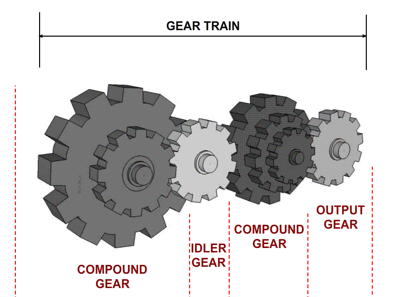
The driver gear drives the follower gear. When the driver gear rotates clockwise, the follower gear will rotate anticlockwise. The idler gear is placed between the driver gear and follower gear to change the rotational direction of the output shaft, or to fill a large gap between the input and output shafts without affecting the speed ratio.

Definitions
Gear Module, m
Gear module refers to the tooth size of a gear.

Pitch Circular Diameter, PCD (mm)
Pitch circular diameter is the imaginary circle that passes through the contact point between two meshing gears. It represents the diameters of two friction rollers in contact and moves at the same linear velocity.

Relationships
Relationship between gear module, pitch circular diameter and number of teeth
Gear module, m = Pitch circular diameter, PCD ÷ no. of teeth, z
Relationship between gear ratio and torque for a pair of gears As gear ratio increases, torque increases.
Relationship between gear ratio (speed ratio) and output speed for a pair of gears
As gear ratio increases, torque increases, output speed decreases, and speed ratio decreases. Hence, gear ratio is inversely related with speed ratio and the equation is as follows: Gear ratio = Speed ratio ^ - 1
Activity 1: Lifting water using gears
Actual gear layout
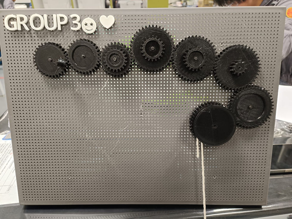
Sketch of the gear layout

Calculation of the gear ratio (speed ratio) Since we had constructed a simple gear train,
Gear ratio = Number of teeth in output gear ÷ Number of teeth in input gear
= 40 ÷ 30
= 1.33
Speed ratio = Gear ratio ^ -1
= 0.752
Number of revolutions required to rotate the crank handle for an elevation of 200 mm
Distance travelled by the water weight = Distance travelled by the output gear = 200 mm
Diameter of the winch = 22 mm
= 2.2 cm
Number of revolutions of the output gear = 20 cm ÷ (π × 2.2 cm)
= 2.8937
Number of revolutions required to rotate the crank = 2.8937 × 1.33
= 3.85
Actual number of revolutions required to rotate the crank = 4
This tells us that more revolutions were required than calculated to rotate the crank handle for an elevation of 200 mm. This is due to several reasons. Firstly, the presence of friction between the board and the gear. Secondly, the presence of friction between the gears. To solve these two problems, we could have loosened the bolts and screws holding the gears together. This is because during the dismantlement of the gears, we noticed scratch marks formed by the turning of gears, indicating that we might have secured our gears too tightly. We can also use gears with a smoother material, as the 3D-printed gears were rather rough.
We could also have utilised a compound gear train setup and arranged our gears in such a way that will increase our gear ratio, and in turn, torque. This can then decrease the strength and force required to turn the crank handle and in turn, the number of revolutions required to rotate the crank.
Video of the turning of the gears to lift the water bottle
Activity 2: Hand-powered fans
Sketch of the gear layout
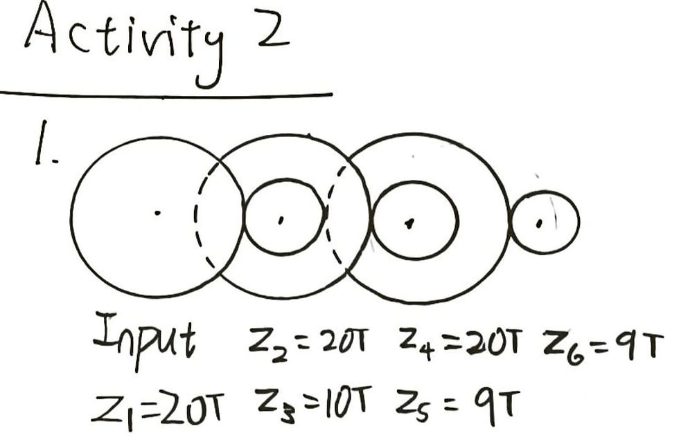
Speed ratio
Gear ratio = (z₃/z₁) × (z₅/z₂) × (z₆/z₄)
= (10/20) × (9/20) × (9/20)
= 0.10125
Speed ratio = Gear ratio ^ -1
= (0.10125)^ - 1
= 9.88
Turbine rotations per crank
Theoretical no. of rotations = Speed ratio
= 9.88
Total rotation of the turbine after 3 cranks = 29
Actual no. of rotations = 29 ÷ 3
= 9.67
Hence, efficiency = (9.67 ÷ 9.88) × 100 %
= 97.9 %
The efficiency, although high, is not 100 % due to the effect of air resistance experienced by the fan blades, as well as the loss of energy through friction that resulted from the motion of the gears.
Video of the hand-powered fan in operation for one crank of the handle
Design proposal to improve the hand-powered fan
To improve the hand-powered fan in terms of its number of rotations per crank, the input gear can be changed to another gear of bigger size that has a higher number of gear teeth, and the output gear can be changed to another gear of smaller size that has a lower number of gear teeth.
This is because Speed ratio = Gear ratio ^ -1 = Input gear teeth ÷ Output gear teeth. By doing the above, the speed ratio can be increased, increasing the number of rotations per crank as a result. The calculations below prove this reasoning.
Initially | After changing z₁ to 30 T and z₆ to 5 T |
z₁ = 20 T z₂ = 20 T z₃ = 10 T z₄ = 20 T z₅ = 9 T z₆ = 9 T Speed ratio = 9.88 Number of rotations per crank = 9.88 | z₁ = 30 T z₂ = 20 T z₃ = 10 T z₄ = 20 T z₅ = 9 T z₆ = 5 T Gear ratio = (z₃/z₁) × (z₅/z₂) × (z₆/z₄) = (10/30) × (9/20) × (5/20) = 0.0375 Speed ratio = Gear ratio ^ -1 = (0.0375)^ - 1 = 26.67 |
Hence, the new number of rotations per crank will be 26.67. This means that every time the handle is cranked, the turbine will rotate 26.67 times.
Learning Reflection
Prior to this practical, I did not try to understand what gears are, because they were already so prominent in our life and I had thought that their concept was fairly simple; they just turn.
One example is within our correction tapes.

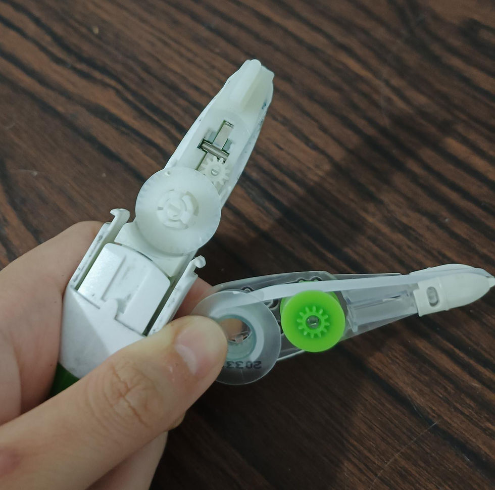
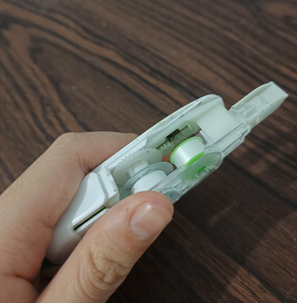
However, after this practical, I have come to learn that there is actually more to gears than just them being able to turn. There are actually theories and calculations involved to allow them to be used for different scenarios or purposes.
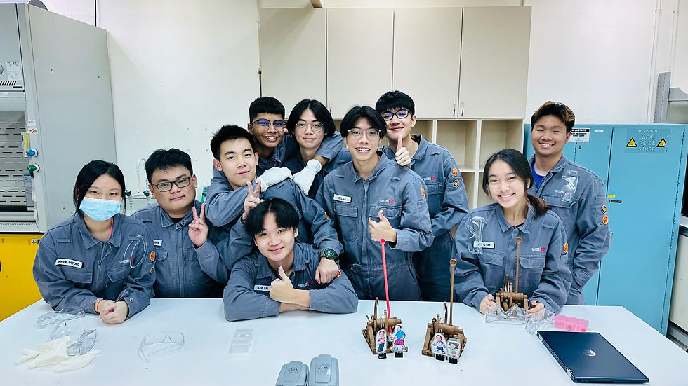
During the practical, I was helping my groupmates with both the activities. Brice and Jian Lun were doing Activity 1, while Joel and Jian Ye were doing Activity 2. I helped with the setup of Activity 2 initially, and there were little to no hiccups during the setup. Afterwards, I helped with the troubleshooting of Activity 1, as a problem arose regarding the difficulty to turn the gears when the input gear handle is bring turned.
After some investigation, we realised that it might be due to us securing the gears to the board (by using screws and nuts and an allen key) too tightly. To solve the problem, we loosened up the bolts and the gears showed an improvement in its turning. We had also relocated the output gear, as it was touching one of the idler gears, resulting in it not being able to turn initially.
Also, my team and I had broken the fan blades (from dropping it) and the gear handle (for turning it too hard). Should we have been more considerate of how fragile the components are, since they are 3D-printed, we could have avoided such an incident. Nevertheless, we managed to fix it by gluing the broken parts back together.
In conclusion, the practical ran smoothly for my team and I, as we had all watched the pre-experimental videos on Brightspace. This told us about how important preparing for an experiment or practical beforehand is, as should we not have done so, we would be at a loss of what to do. However, despite the practical having run smoothly, I believe that we could have improved on our Activity 1. This is because we only had a gear ratio of 1.33, due to us using a simple gear train and not alternating the different gear sizes in an attempt to manipulate the gear ratio. Well, another group had a gear ratio of above 20! Should we have done calculations to manipulate the gear ratio beforehand, we could have saved our energy in turning the gear handle, as all of us had difficulties doing so, and turning the gear handle had even resulted in red and painful fingers.


can u update me when u finish ur blog? <3